|
Andy Connor & Wilson Siringoringo, Auckland University of Technology, New Zealand
andrew.connor@aut.ac.nz, wilson.siringoringo@aut.ac.nz
Nick Clements & Nick Alexander, Building Integration Services Company (bisco), New Zealand
nickc@bisco.co.nz, nicka@bisco.co.nz
Connor, A., Siringoringo, W., Clements, N., Alexander,
N. (2007, Dec), Building Services Integration: A Technology
Transfer Case Study. Bulletin
of Applied Computing and Information Technology Vol. 5, Issue
2. ISSN 1176-4120. Retrieved
from
ABSTRACT
This paper details the development of a relationship between Auckland
University of Technology (AUT) and the Building Integration Software
Company (bisco) and how projects have been initiated that add value to
the bisco product range by conducting applied research utilising
students from AUT. One specific project related to producing optimal
layout designs is discussed.
Keywords
Technology Transfer
1. INTRODUCTION
Technology transfer is the process of developing practical applications
for the results of scientific research. In other words, the aim of
technology transfer is to ensure that the knowledge generated through
research has commercial value and that the knowledge itself is moved
from the research domain into the industrial domain. The Technology for Industry Fellowships offered by Technology New
Zealand are one mechanism for promoting technology transfer as well as
developing students' skills and knowledge within commercial R&D
environments that are relevant to their expertise. To utilize this funding source to its full advantage,
there is a need to establish a relationship between the academic
institution and the company, and to develop a shared understanding of
aspirations and how the project can be designed to allow all of these
aspirations to be met.
2. THE BUILDING INTEGRATION SOFTWARE COMPANY
Building Integration Software Company (bisco) Ltd is a business
enterprise whose main product is information management software for the
residential house construction industry. The organization has been
founded by people who had identified the need of such centralized
information management from their own extensive experience in the
construction industry. The premise of such a need is the fact that a typical house building
project involves a number of different parties such as an architect,
builders, city council, and others, who work in different ways and run
their organizations for different goals. Although many have already
adopted computer-based information systems, there is no automated means
for communication with other parties. Only verbal and paper-based forms
of communication are hitherto available to those parties to exchange
information. It is not surprising that substantial amounts of money and
effort are wasted during a project due to the lack of reliable and
efficient communication systems.
The core business of bisco is developing software to accommodate such
communication needs. At the time of the writing, the prototype of the
software is drawing close to finish, after which it will undergo a
series of live tests before it is finalized for release to the market.
The software has been given a commercial name bisco Office™. bisco Office™ manages a range of information that is very diverse in
terms of representation and usage. A typical bisco Office™ database for
a house building project will include pictures and text, Computer Aided
Design (CAD) drawings, letters, invoices, and a host of other documents.
Such documents take various physical forms such as computer files,
paper, and e-mail correspondence. Figure 1 shows the different parties
interacting through the bisco Office™ software.
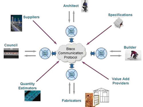
Figure 1. Information exchange using bisco Office™
software
The geometric data stored in the CAD drawings assumes overriding
importance in the house building projectâs web of information. Many
important documents created during the lifetime of the project, such as
cost estimates, specification documentation, or project plans, are
actually spawned from the CAD models. Consequently, the software
engineering aspect of bisco Office™ at the current stage revolves
primarily on extracting and making use of the CAD data.
The bisco Office™ product provides a framework for improving
information exchange in the building services industry and for
integrating existing tools in a more efficient manner. The framework
also allows for the integration of new tools, such as the material
optimisation approach outlined in section 3. However, the success of the
approach depends on its ease of use and therefore a usability study is
being undertaken which will be detailed in future publications.
3. MATERIAL LAYOUT OPTIMISATION PROJECT
3.1 Overview of Project Scope
Optimum two-dimensional layout is a class of problems encountered in
many industries. The problems are characterized with the need to pack
non-overlapping shapes in an enclosed plane with the aim of minimizing
the area outside the boundaries of the shapes, therefore maximizing the
utilization of the material in the base sheet. The two-dimensional
layout problem exists in several variants. Among them are the sheet
layout problem, bin packing and strip packing problems,
optimum floor
plan problem, and cutting stock problem.
The optimum two-dimension layout problem has an application in a wide
range of industries. Industries such as textile, wood, glass, and
steelworks regularly encounter the problem of cutting the material most
efficiently so as to minimize waste. In a different context, very large
scale integration (VLSI) design requires arranging a large number of
transistors and other modules in a rectangular silicon chip.
A rather unique variant of the optimum two-dimensional layout problem
is found in the construction industry. A polygon shaped area such as
wall or ceiling is to be tiled with covering sheet material such as
Gibraltar board or plywood. With such tiling, it is essential that the
entire surface is covered with no gaps or overlaps. The panels are
obtained from the supplier in a range of fixed size rectangles.
Typically the individual panel is much smaller than the area to be
covered. It is also anticipated that the enclosing area may have an
irregular outline.
The problem is demonstrated in Figure 2. To keep the construction
expenses under control, the builder must arrange the panels in a way
that keeps the cost variables low. Such parameters include the number of
panels allocated, the amount of discarded off cuts, and the amount of
effort required for cutting the panels.
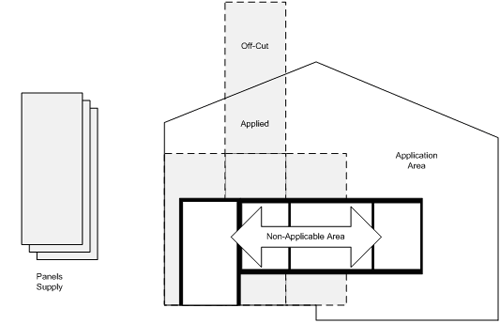
Figure 2. Wall overlay with fixed size panels
A similar problem has been encountered in the shipbuilding industry,
particularly in cutting steel sheets to cover various parts of the ship.
Adamowicz and Albano defined the problem for the operator (Adamowicz &
Albano, 1976):
- A set of standard rectangular sheets of steel is provided
- An order is given to produce various types of shapes which include
rectangular and irregular shapes
- It is required that no two shapes may overlap
- Waste is minimized
When the panel is homogenous, such as with sheet metal, it is
desirable to reuse the off cuts to cover irregular regions at other
places, as this has the potential to reduce the total number of sheets
required. A particular example was made by Sibley-Punnett and Bossomaier
(2001) regarding the reuse of off cuts from corrugated iron roofs. The
justification for such effort is provided by the high cost of delivering
the roofing material.
The diversity of materials used for constructing a building provides
no guarantee that such homogeneity exists for materials used for a
particular area. The implication is that the constraints for a
particular section of the building cannot be predetermined. In response,
a computer program used to resolve such problem must be capable of
finding the solution under a varying set of constraints to allow it to
be used for any specific instance of the general problem.
Closer examination reveals that the polygon overlay problem is
composed of two sub-problems which must be resolved sequentially,
although each sub-problem still belongs to the same two-dimensional
layout optimization. For a given enclosed area and a given dimensions of
rectangular panels, the requirement is twofold:
- Find the optimum arrangement of whole panels in which the covered
area within the enclosure is maximized. The by-product of this process
is a set of irregular shapes which represent the remaining exposed
areas.
- Resolve how such irregular shapes can be nested within the minimum
number of panels. Shapes that are bigger than the panel itself are cut
at angles parallel with the rectangleâs axes to allow such nesting.
This decomposition into two sub-problems can potentially mask the
complexity of the task of finding the optimum solution. It is important
to recognize that in the construction industry, the actual size of the
panels is in itself a design parameter. In some applications, the panel
size will remain fixed for the two sub-problems whilst for other
applications the panel size could potentially be varied. With this in
mind, it becomes apparent that the problem is complex with potentially
many locally optimum solutions.
At the end of the calculation process, the desired output consists of
numerical and graphical information:
- The total number of panels, consisting of panels to be fitted whole
and the remainder to be cut to produce the irregular shapes
- The nesting plan with which irregular shapes are cut from whole
panels
- The area overlay plan with which whole panels and irregular cuts are
fitted to the enclosed area
It is important to note that although the two sub-problems are
similar, they are resolved with mutually unrelated and potentially
conflicting objectives. As an example, the lowest cost solution for
first sub-problem may be to cover as much area as possible with the
least number of panels. However, the optimum solution for the second
sub-problem may be the least amount of cutting (the panel may actually
be a marble or granite slab, for instance). Hence a cheap solution in
the first phase may lead to expensive penalties in the second.
3.2 Project Motivation
Apart from reducing the waste and reducing the associated cost,
automating the panel placement design also greatly assists the builder
in calculating the required material. When the calculation is done by
hand, the common practice is to have a human expert work on the layout
and to estimate the number of panels needed to cover a particular part
of the building. A few extra panels must then be provided to anticipate
the error in the calculation. As the solution only applies to a particular part of the building,
the work must be repeated for all other parts as well. The process
becomes more tedious when different sizes of the panels are available to
choose from. Exploring more than a few different configurations by hand
is therefore an impractical proposition.
In general, the cost of the materials is low so that the additional
time required to optimise the panel layout manually cannot be justified
by the potential cost savings.
The low value means even using computer optimisation would not be
viable should it require additional work.
As bisco Office™ makes the required geometric and building
information easily available for use by an optimisation function the
process becomes a viable option.
Another inherent problem in complex problems is the lack of guarantee
that an optimum solution in the first phase will lead to an optimum
solution of the entire problem. Coupled with the absence of a-priori
knowledge about the cost of the subsequent phase, exploring the
less-than-optimum first-phase solutions becomes a necessity. Seen in
this light, making the process automatic offers the potential of
discovering better solutions than those obtained by hand.
When computers are used, more possible solutions can be explored both
for individual parts of the building as well as the sum of all those
parts. The desired effect is that by providing the raw information to
the software, in the form of a CAD model of the entire building, the
builder obtains a detailed and accurate plan about the number of panels
required and how they should be cut and installed for the whole
structure. In addition to this, some suppliers offer to package the sheet
materials into “room lots” allowing their placement by crane into the
room space prior to the erection of the building walls saving labour
carrying the individual sheets by hand.
Use of this technology will allow the use of length optimised
packets increasing the effectiveness of this service.
3.3 Project Achievements
The project has been a great success with regards not only the
outcomes of the research, but also in terms of transferring research
knowledge into the industrial domain. Initially, the research focused on
the underlying geometric operators required to manipulate the CAD data
and panel shapes to allow the optimisation process to be realised. The project also developed a range of algorithms that could be
applied to the solution of layout optimisation problems in the building
services domain. A comparative study has been undertaken to see which of
the algorithms best meets the needs of the industry and this will be
taken forward in the commercialisation phase of the project.
A software tool to perform the layout optimisation has been
developed, as shown in Figure 3.
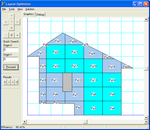
Figure 3. Layout optimisation software tool
3.4 Project Status
This project, which is now complete, has been undertaken by a student
on the Master of Computer and Information Sciences programme at Auckland
University of Technology. The comparative study of different algorithms
is complete, which has allowed the student to submit their Masters
thesis for successful examination. The software tool used in the
research is now being integrated into the bisco product range. It is expected that the tool will be applied into a wide range or
sheet or tiling situations within the build including wall linings,
flooring material, external sheet cladding, and roof cladding.
4. CONCLUSIONS
The success of the material layout optimisation project has led to a
strengthening of the relationship between bisco and AUT, and as a result
further projects are being undertaken with both a short term and a
longer term focus. Of particular note, the success of the material
layout optimisation project has led to another successful grant from
Technology New Zealand to extend the work into new areas, and allowing
the student to enrol for a Doctoral programme. This opportunity will
further increase the value of is research but looking at not only the
impact of sheet layout decisions on the whole building, but to
investigate how the building structure and layout can be modified to
improve the design targets specified by the architect.
At present, one of the key challenges with the bisco software is the
need to address the uptake of the technology with the end users,
particularly mobile users. One of the further projects currently being
undertaken is addressing the usability issues of TabletPC technology and
other mobile devices and address whether this can assist in the
interactions in the supply chain relating to building services
activities.
There is opportunity to further increase the value of this research
by looking at the impact of sheet layout decisions on the building. The
sheet layout determines much of the underlying structure, for example
the placement of studs or joists, and these have a material impact on
the cost of the building. If we can better integrate the decision making
processes that affect the layout of sheeting and the required support
structures the potential should exist to reduce building costs without
reducing the utility value of the structure.
5. ACKNOWLEDGEMENTS
The research outlined in this paper was funded by Technology New
Zealand through the Technology for Industry Fellowships scheme, under
grant number BISC0502.
REFERENCES
Adamowicz, M., & Albano, A. (1976). Nesting
Two-Dimensional Shapes In Rectangular Modules. IEEE Transactions on
Systems, Man and Cybernetics, 8(1), 27-33.
Sibley-Punnett, L., & Bossomaier, T. (2001).
Optimisation techniques for roof layout. Proceedings of IEEE Region 10
International Conference on Electrical and Electronic Technology, 50-56.
Copyright © 2007 Andy Connor, Wilson Siringoringo,
Nick Clements, Nick Alexander
The author(s) assign to NACCQ and educational non-profit institutions a
non-exclusive licence to use this document for personal use and in
courses of instruction provided that the article is used in full and
this copyright statement is reproduced. The author(s) also grant a
non-exclusive licence to NACCQ to publish this document in full on the
World Wide Web (prime sites and mirrors) and in printed form within the
Bulletin of Applied Computing and Information Technology. Authors retain their individual intellectual property rights. |
